Getting Started with Embedded Systems: Blinking an LED
Learn to blink an LED on an ARM Cortex-M microcontroller using both C and Rust. Includes wiring, code examples, flashing instructions, and debugging tips.
Embedded systems power the devices all around us—from microwaves to wearables—and learning to make something “come alive” is one of the most satisfying first steps. In this post, we’ll walk through a basic but essential tutorial: blinking an LED on an ARM Cortex‑M microcontroller. This simple project introduces you to:
- Hardware basics (wiring & microcontroller pins)
- Bare‑metal C programming (Chapter 7 example)
- Rust on embedded (
#![no_std]example from Chapter 10) - Building, flashing, and debugging
1. Hardware Setup
You’ll need:
- A development board (e.g. STM32F0 Discovery, Nucleo‑F103, or any Cortex‑M “blue pill”)
- One LED (or you can use the board’s onboard LED, usually on PA5 or PC13)
- A 220 Ω resistor
- Breadboard and jumper wires
Wiring:
Connect the LED’s anode (+) through the resistor to the microcontroller’s GPIO pin (e.g. PA5). Connect the cathode (–) to GND.
2. Blinky in C (Bare‑Metal)
This example uses direct register access—no OS or HAL. It corresponds to the “Blinky LED example” in Chapter 7.
#include <stdint.h>

// Base addresses for GPIOA (STM32F103 example)
#define PERIPH_BASE   0x40000000UL
#define APB2ENR       (*(volatile uint32_t*)(PERIPH_BASE + 0x18FC))
#define GPIOA_CRL     (*(volatile uint32_t*)(PERIPH_BASE + 0x1080))
#define GPIOA_ODR     (*(volatile uint32_t*)(PERIPH_BASE + 0x108C))

void delay(volatile uint32_t count) {
    while (count--) {
        __asm__("nop");
    }
}

int main(void) {
    // 1. Enable GPIOA clock (bit 2 of APB2ENR)
    APB2ENR |= (1U << 2);

    // 2. Configure PA5 as push‑pull output, max speed 2 MHz
    GPIOA_CRL &= ~(0xF << (5 * 4));     // clear CNF/MODE
    GPIOA_CRL |=  (0x2 << (5 * 4));     // MODE5 = 10 (output, 2 MHz), CNF5 = 00

    while (1) {
        // 3. Toggle PA5
        GPIOA_ODR ^= (1U << 5);
        delay(1U << 20);
    }

    // Should never reach here
    return 0;
}
Build & Flash:
- Install
arm-none-eabi-gcctoolchain. - Reset the board and watch the LED blink!
Flash via ST‑Link:
st-flash write blinky.elf 0x8000000
Compile with:
arm-none-eabi-gcc -mcpu=cortex-m3 -mthumb -Os -nostartfiles \
  -Tstm32f103c8t6.ld -o blinky.elf blinky.c
3. Blinky in Rust
If you prefer Rust’s safety guarantees, you can blink an LED with #![no_std] on bare metal (see Chapter 10).
#![no_std]
#![no_main]

use cortex_m_rt::entry;
use panic_halt as _; // halt on panic
use stm32f1xx_hal::{delay::Delay, gpio::gpioc::PC13, gpio::Output, gpio::PushPull, pac, prelude::*};

#[entry]
fn main() -> ! {
    // 1. Take ownership of peripherals
    let dp = pac::Peripherals::take().unwrap();

    // 2. Constrain & split clocks
    let mut flash = dp.FLASH.constrain();
    let mut rcc = dp.RCC.constrain();
    let clocks = rcc.cfgr.freeze(&mut flash.acr);

    // 3. Acquire GPIOC and configure PC13 as push‑pull output
    let mut gpioc = dp.GPIOC.split(&mut rcc.apb2);
    let mut led: PC13<Output<PushPull>> = gpioc.pc13.into_push_pull_output(&mut gpioc.crh);

    // 4. Setup delay
    let mut delay = Delay::new(cp.SYST, clocks);

    loop {
        // Toggle LED
        led.set_low().unwrap();
        delay.delay_ms(500_u16);
        led.set_high().unwrap();
        delay.delay_ms(500_u16);
    }
}
Build & Flash:
# Add target
rustup target add thumbv7m-none-eabi

# Compile
cargo build --release --target thumbv7m-none-eabi

# Flash (using cargo‑embed or probe‑runner)
cargo embed --release
4. Debugging Tips
- USART printf: Use a serial port for
printf‑style debugging (Chapter 20). - GDB over SWD: Connect with OpenOCD and
arm-none-eabi-gdb. - Logic Analyzer: Verify the LED’s timing and waveform.
5. Next Steps
Once you’ve mastered blinking:
- Timers & PWM (Chapter 12): Vary LED brightness or drive servos.
- Analog I/O (Chapter 13): Read sensors and adjust behavior.
- RTOS (Chapters 17–18): Schedule multiple tasks, blink multiple LEDs, handle button inputs smoothly.
Blinking an LED may seem trivial, but it introduces you to the full embedded‑development workflow: writing code, configuring registers (or HAL), building, flashing, and debugging. From here, you can confidently tackle more complex projects—sensors, communication interfaces, and real‑time systems.
If you want to Learn More About Embedded Systems using C, please have a look at this Book:
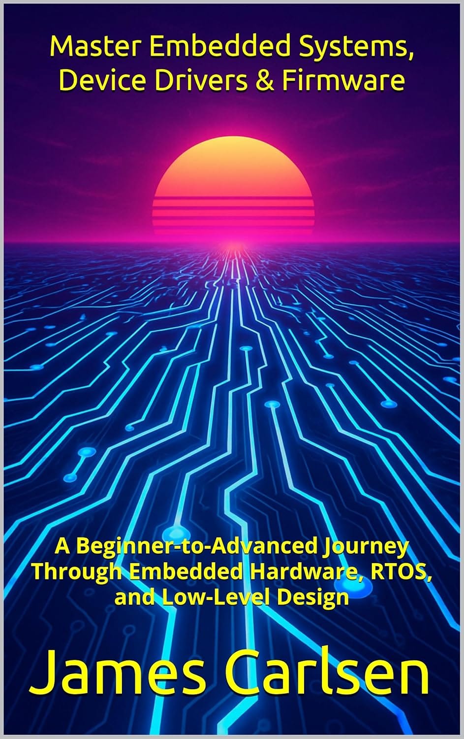
Master Embedded Systems, Device Drivers & Firmware
Download the free sample chapters now